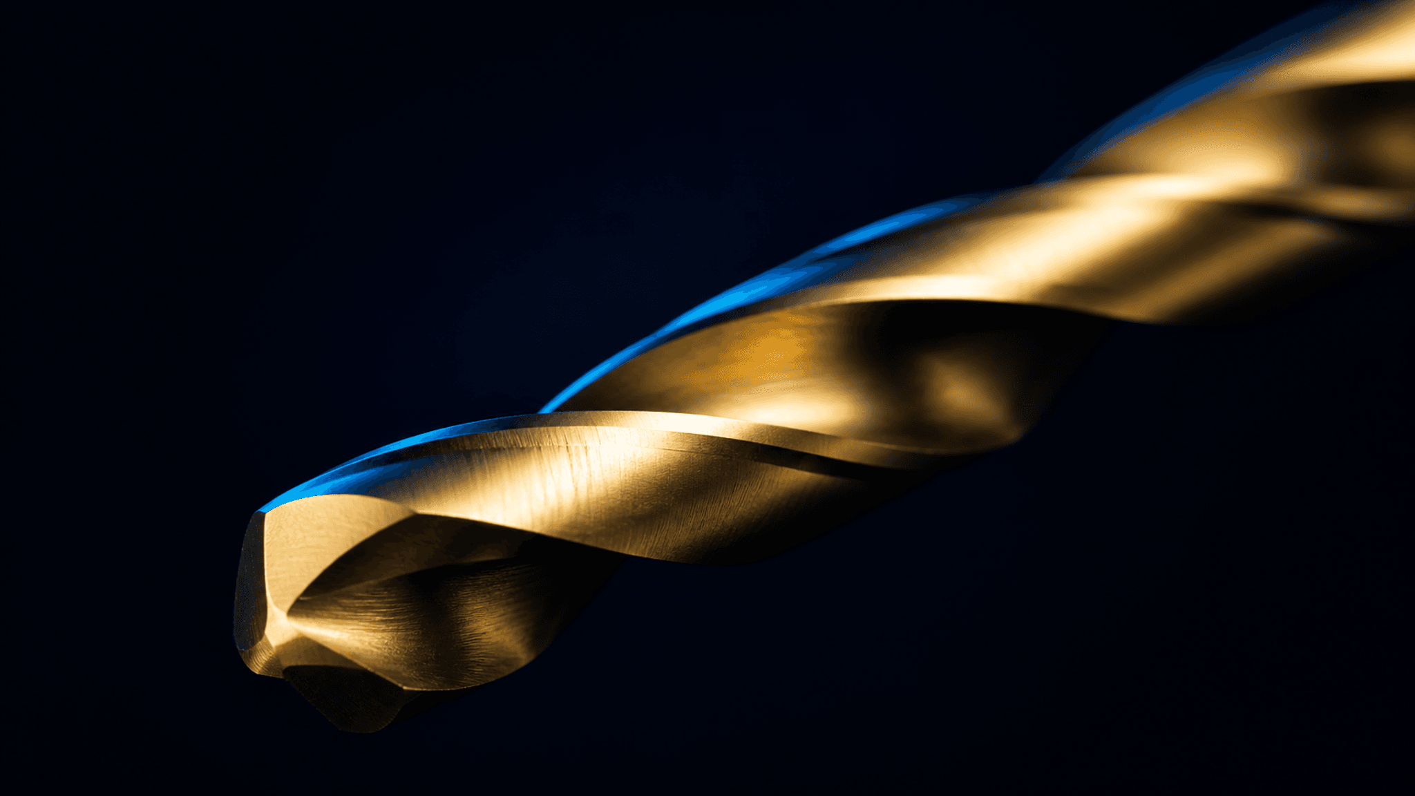
The conventional implant drilling protocol has barely changed in sixty years: start with a pilot drill, step up through an ascending sequence of stainless-steel twist drills at 800–1,200 rpm under irrigation, and hope the osteotomy ends up where the plan said it would.
Meanwhile, almost everything around it has changed: guided surgery, CBCT planning, osseodensification and immediate protocols. So it is worth asking the uncomfortable question: is the classic ascending sequence still the best way to prepare an osteotomy, or simply the most familiar?
A recent line of thinking, low-speed drilling combined with a crown-down sequence and harder cutting materials, argues for the latter. Here is the reasoning, what the literature supports, and where the open questions remain.
Interactive · Fig. 1Two ways to prepare the same osteotomy
Step 1. A wide carbide drill clears the rigid cortical layer, and stops there.
Two tissues, one drill?
Start with the anatomy, because the whole argument rests on it: cortical and trabecular bone are not the same material, and treating them as one is the central weakness of the conventional sequence.
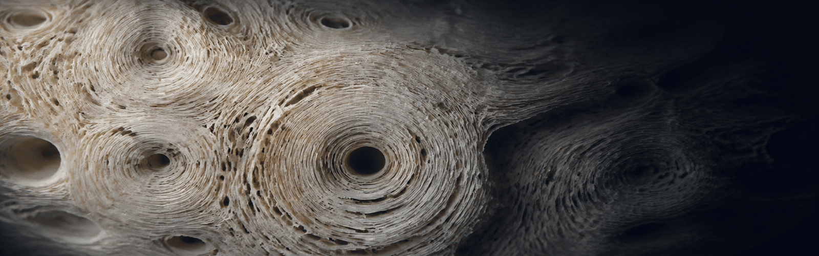
Elasticity. Trabecular bone, as a porous structure, can deform substantially. The manufacturer-supplied material cites apparent deformation up to about 50%, while dense cortical bone tolerates roughly 2% before failure. Elastic tissue can deform around an inefficient edge rather than being cleanly cut, producing irregular walls and less dimensional accuracy.
Interactive · Fig. 2Cortical vs. trabecular: the numbers that drive the design
Cortical bone
- Rigid. Small dimensional discrepancies can prevent complete implant seating.
- Innervated. Excessive compression can add trauma and postoperative pain.
- Lower vascularity. Supply comes through the periosteum and intracortical channels.
- Crown-down answer: clear it first with the largest, strongest carbide drill.
Trabecular bone
- Elastic. It can deform around an inefficient edge instead of shearing cleanly.
- Rebounding walls. Sidewall friction becomes heat when cutting is poor.
- Highly vascular. Blood, marrow and cells support healing.
- Crown-down answer: prepare it second, undersized and under lower load.
Rigidity. Cortical bone presents the opposite problem. A small dimensional discrepancy can stop an implant short of full seating, while excessive compression can produce microfracture, added surgical trauma and postoperative pain.
Vascularity. Trabecular bone is highly vascular, carrying marrow, plasma and cellular elements involved in healing. Cortical bone has comparatively less vascularity, supplied by periosteal and intracortical channels. Different elasticity, rigidity and biology make a tissue-specific sequence mechanically plausible.
The case for slowing down
“Low-speed drilling” has no single agreed threshold. Published protocols range from roughly 50 to 300 rpm, with some specifically describing 50–150 rpm without irrigation [3,9]. It is more useful to understand it as osteotomy preparation performed far below conventional speed.
1. Less dependence on irrigation. External irrigation can lose effectiveness in guided surgery, deep osteotomies and restricted access. Lower speed produces frictional heat more slowly, but rpm alone is not a thermal guarantee; sharpness, material, diameter, pressure, drilling time, bone density and chip evacuation all matter [3,4,7,12].
2. Autogenous bone collection. Low-speed drilling without irrigation increased the frequency and weight of autogenous bone harvested from drill flutes in one randomized clinical trial. The study did not establish a clinical healing benefit [9].
3. Preserving the osteotomy environment. Without constant lavage and suction, collected bone remains available for local grafting. Whether this changes healing or implant outcomes remains unproven [9].
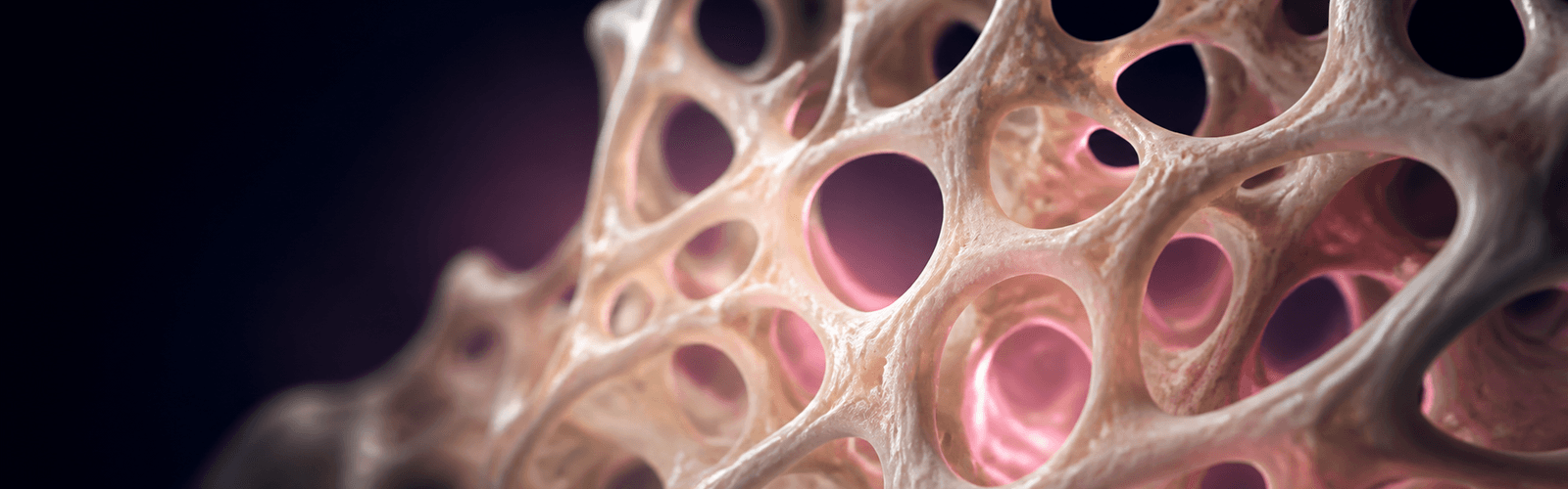
Chart · Fig. 3Where each protocol operates
Why you cannot just turn the dial down
At 200 rpm, each rotation has to cut. A drill that is not sharp enough, or cannot evacuate chips, forces the clinician to push harder and remain in bone longer, recreating the heat problem that low speed was meant to address. Drill wear is a documented contributor to heat generation [2,4,5,13]. In the manufacturer's bench test on dental stone, a steel drill's edge had worn flat after twenty 3 mm osteotomies; that is manufacturer evidence, not a clinical durability trial.
Slowing a conventional kit is not the same as using a purpose-designed low-speed protocol.
Harder material, a new problem
Tungsten carbide has been used as a hard cutting material since Krupp introduced WIDIA in 1926 [6]. Its edge retention and thermal conductivity are part of the manufacturer's rationale for cutting at about 200 rpm.
But solid carbide brings its own failure mode: brittleness. Steel can bend and absorb overload; carbide does not plastically deform. Lateral or torsional stress on a small-diameter carbide drill can lead to sudden fracture. Simply rebuilding the classic pilot-to-final sequence in carbide would expose the smallest drill to the highest cortical resistance.
The crown-down answer: two drills, two bone types
The Crown Down Kit reorganizes the sequence so that the material's weakness is less exposed.
Cortical first, with the stronger drill. A larger-diameter carbide cortical drill clears the rigid cortical layer first, where resistance is highest.
Trabecular second, with a smaller drill. Only after the cortical restriction is relieved does an undersized carbide drill prepare the deeper trabecular portion under lower mechanical load.
The intended benefit is not only fewer instruments. Each drill meets the tissue it was designed to prepare. With the cortical plate relieved and the trabecular portion deliberately undersized, implant insertion can condense elastic trabecular bone without being blocked coronally. Whether that translates into better clinical outcomes requires protocol-specific evidence.
The kit · Manufacturer imagesEight drills, usually two per osteotomy
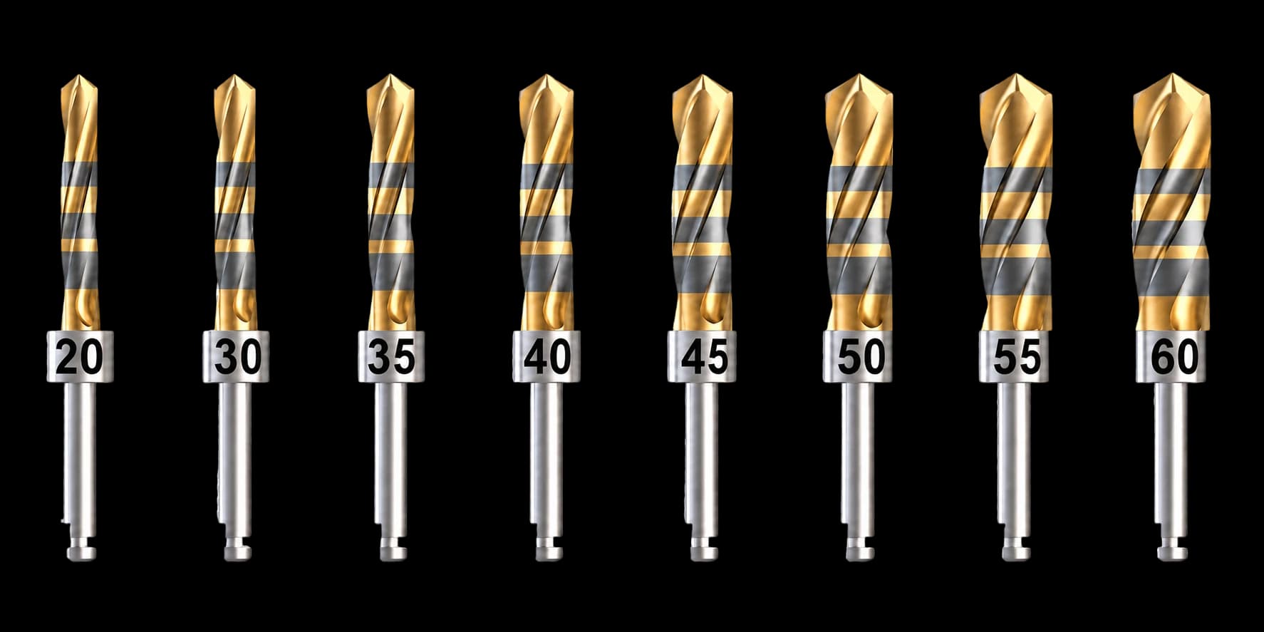
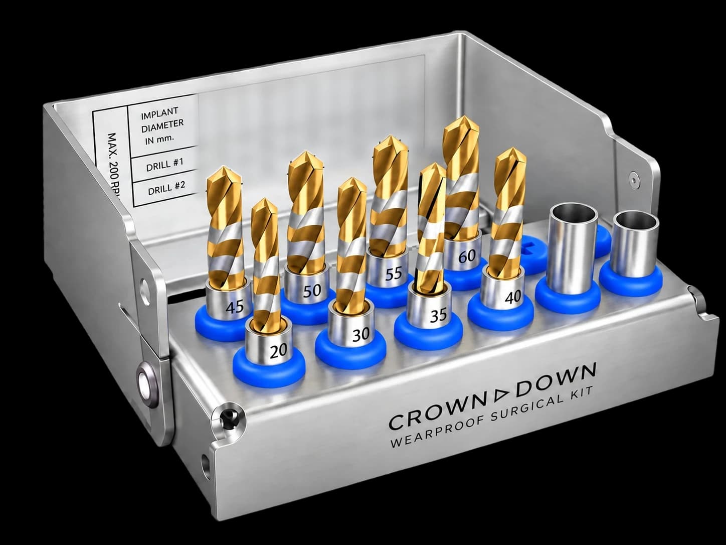
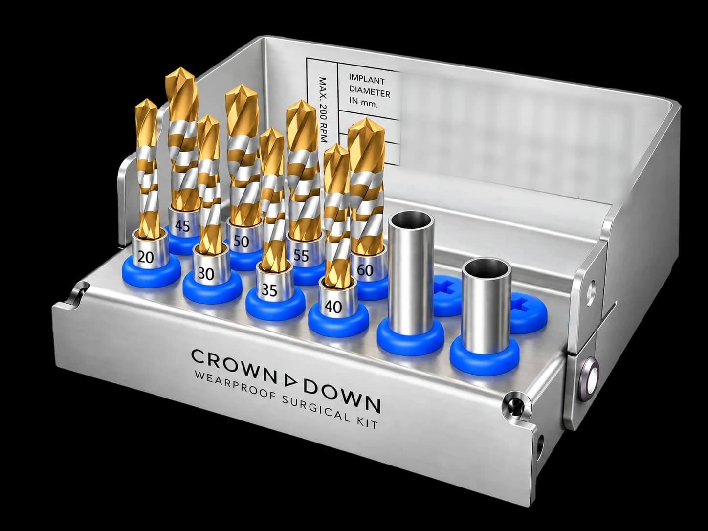
Product images supplied by Crown Down Kit; the lid chart is blurred by Periospot. Use your implant system's row in Fig. 5, and where it differs from the lid chart, confirm the drills with the manufacturer before clinical use.
Cortical portion first with the wider drill, then the narrower drill to the planned depth. The drill sizes in the clip are an example: choose the pair for your implant system with Fig. 5 below and the manufacturer's instructions.
Video: Crown Down Kit. Silent animation, 22 s.
Interactive · Fig. 4One drill, six lengths: the ABCD depth code
Each crown-down drill carries laser depth bands labelled a–d. Watch the drill reach each implant length, or choose one, and read the pair of bands the manufacturer says to align with the bone crest.
For a 6 mm implant, stop when band pair Bb sits at the bone crest.
The same six reference depths and codes as Fig. 4. The drill in the clip is a reference illustration, not drawn to scale: use it to learn the code, not to judge the spacing of the bands. Fig. 4 above draws the same codes on a millimetre scale.
Video: Crown Down Kit. Silent animation, 21 s.
Irrigation, heat and collected autogenous bone
The irrigation-free protocol depends on carbide continuing to cut efficiently at low rpm. The thermal-threshold literature remains the clinical reference point, and technique still matters: sharpness, pressure, time in bone and bone density all affect heat generation [1,2,3,4,5,7,11,12].
The practical side effect is bone collection. Without saline washing chips into suction, the flutes retain autogenous bone. A randomized clinical trial compared low-speed drilling without irrigation with high-speed drilling under irrigation for bone harvested during implant bed preparation [9]. This does not establish superiority of the complete Crown Down Kit protocol.
Interactive · Fig. 5Will it work with my implant system?
The manufacturer's protocol charts cover 29 implant systems. Choose a system and implant diameter to retrieve the recommended cortical and trabecular drills.
Wide carbide drill. Clears the rigid cortical layer.
Undersized carbide drill. Prepares the elastic depth at ≤200 rpm.
AB Dental, diameter 3.5 millimetres: cortical drill #35, trabecular drill #20.
View AB Dental as a table
| Implant Ø (mm) | Drill #1 · cortical | Drill #2 · trabecular |
|---|---|---|
| 3.5 | #35 | #20 |
| 3.75 | #40 | #20 |
| 4.2 / 4.5 | #45 | #35 |
| 5.0 | #50 | #40 |
| 6.0 | #60 | #50 |
The honest limitations
It is a workflow change. Moving away from the pilot-to-final sequence after years of muscle memory is a meaningful adjustment.
Direction correction is constrained. The opportunity to correct osteotomy direction after a test-pin radiograph is more limited; CBCT planning and guided surgery help make the intended path predictable.
The evidence base is young. The mechanical rationale is plausible and the supporting literature on heat, drill wear and autogenous bone is real, but protocol-specific clinical evidence still needs to accumulate. “Wear-resistant” is the honest claim; no drill is wear-proof.
Bottom line
The conventional ascending protocol prepares cortical and trabecular bone with the same tools and depends on irrigation to control frictional heat. The crown-down approach clears cortical bone first with a stronger carbide drill, then prepares the trabecular depth under lower load at low speed without irrigation. It will not suit surgeons who want their workflow untouched. For clinicians willing to reconsider the sequence, it is a technically interesting proposal that now needs more direct clinical evidence.
The eight drill sizes, a drill's cutting end and the three depth stoppers. Product statements in the film are the manufacturer's; Periospot has not independently tested the device.
Video: Crown Down Kit. Excerpt shown without sound, 14 s.
Frequently asked questions
What is a crown-down implant drilling protocol?
It prepares the rigid cortical layer first with a wider drill, then uses a smaller, undersized drill for the trabecular depth. That reverses the familiar pilot-to-final ascending sequence.
Does 200 rpm automatically make implant drilling thermally safe?
No. Temperature also depends on drill sharpness and material, pressure, time in bone, diameter, bone density and chip evacuation. Low speed is one part of a complete protocol, not a safety guarantee.
Can a conventional stainless-steel kit simply be run at low speed?
That is not equivalent to a purpose-designed low-speed protocol. At low rpm, each rotation must cut efficiently; a worn or poorly evacuating drill can increase pressure and drilling time.
How do I choose the drills for my implant system?
Use the interactive chart as a review aid. The generic chart inside the cassette lid can pair drills differently for some systems, so confirm the drills for your implant system with the manufacturer's current instructions before clinical use.
References
- Eriksson AR, Albrektsson T. Temperature threshold levels for heat-induced bone tissue injury: a vital-microscopic study in the rabbit. J Prosthet Dent. 1983;50(1):101-107. Source
- Chacon GE, Bower DL, Larsen PE, McGlumphy EA, Beck FM. Heat production by 3 implant drill systems after repeated drilling and sterilization. J Oral Maxillofac Surg. 2006;64(2):265-269. Source
- Mishra SK, Chowdhary R. Heat generated by dental implant drills during osteotomy: a review. J Indian Prosthodont Soc. 2014;14(2):131-143. Source
- Möhlhenrich SC, Modabber A, Steiner T, Mitchell DA, Hölzle F. Heat generation and drill wear during dental implant site preparation: systematic review. Br J Oral Maxillofac Surg. 2015;53(8):679-689. Source
- Oliveira N, Alaejos-Algarra F, Mareque-Bueno J, Ferrés-Padró E, Hernández-Alfaro F. Thermal changes and drill wear in bovine bone during implant site preparation. Clin Oral Implants Res. 2012;23(8):963-969. Source
- thyssenkrupp company history. WIDIA carbide, introduced in 1926. Source
- Bernabeu-Mira JC, Pellicer-Chover H, Peñarrocha-Diago M, Peñarrocha-Oltra D. In vitro study on bone heating during drilling of the implant site: material, design and wear of the surgical drill. Materials. 2020;13(8):1921. Source
- Coyac BR, Sun Q, Leahy B, et al. Optimizing autologous bone contribution to implant osseointegration. J Periodontol. 2020;91(12):1632-1644. Source
- Bernabeu-Mira JC, Peñarrocha-Diago M, Canullo L, Camacho-Alonso F, Cortes ARG, Peñarrocha-Oltra D. Autologous bone harvested during implant bed preparation: a randomized clinical trial comparing high-speed drilling with irrigation versus low-speed drilling without irrigation. Clin Implant Dent Relat Res. 2024;26(4):724-733. Source
- Burchardt H. The biology of bone graft repair. Clin Orthop Relat Res. 1983;(174):28-42. Source
- Gehrke SA, Bettach R, Taschieri S, Boukhris G, Corbella S, Del Fabbro M. Temperature changes in cortical bone after implant site preparation using a single bur versus multiple drilling steps. Clin Implant Dent Relat Res. 2015;17(4):700-707. Source
- Chakraborty S, Moufti M-A, Kheder W. The effect of dental implant drill materials on heat generation in osteotomy sites: a systematic review. Eur J Dent. 2024;18(1):65-72. Source
- Falisi G, et al. SEM-EDX analysis of metal particles deposition from surgical burs after implant guided surgery procedures. Coatings. 2022;12(2):240. Source